In the previous lectures, general description on farm pond is covered along with detailed design of embankment type of farm pond. In this lecture, design and construction details of dugout farm pond is discussed. A well design serves as a valuable asset for integrated farming and should be properly constructed after thorough design and planning.
Designing Dugout Farm Ponds
The design of farm ponds includes determination of capacity, its location, utilization plan and shape and size.
Catchment and Cultivable Area Ratio
This ratio is particularly important to determine the optimal size of pond based on the available catchment and the utilization of stored water in the cultivable area. The ratio between catchment (Aca) and cultivable area (Acu) also influenced by runoff coefficient and runoff efficiency factor. This ratio indicates the amount of cultivated area in the total catchment area. This ratio is given as (Critchley et al., 1991):
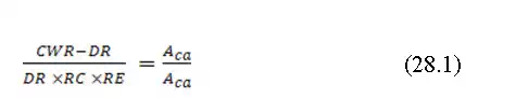
Where CWR is the crop water requirement, DR is the design rainfall, RC is the runoff coefficient, RE is runoff efficiency factor, Aca is the catchment area and Acu is the cultivable area.
Crop water requirement depend upon the type of crop and location specific climate and can be calculated from standard equations and models.
Runoff coefficient is the runoff to rainfall ratio. It is amount of surface flowover the ground. The coefficient is governed by slope, soil type, vegetation, AMC, and rainfall characteristics (intensity, frequency and duration). Typically this coefficient ranges between 10 to 50%. Larger catchment has lower runoff coefficient than smaller catchment (1-5 ha). The runoff coefficients are site specific and should be determined locally.
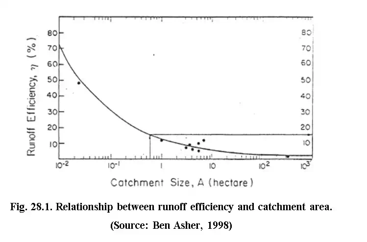
Efficiency factors address the issue of uneven distribution of the runoff water within the field. The uneven distribution occurs due to differential infiltration and percolation and surface depression. When the cultivated area is leveled and smooth, the efficiency is higher. Generally micro- catchment systems have higher efficiency. The efficiency can be determined using the graphical relationship between runoff efficiency and catchment area (Fig. 28.1).
The basic principle of design is to produce a satisfactory functional structure at a minimum cost. To minimize the cost, the pond should be designed for its maximum utilization considering the three strategies for irrigation particularly in rainfed agriculture (Reddy et al., 2012).
Meeting the crop water requirement of growing season.
Meeting water requirement of critical irrigation (CRI) during the critical stages of crop growth.
Meeting water requirement in cropping system approach e.g. irrigation during critical stages of kharif crop plus water requirement of Rabi crop such as vegetables.
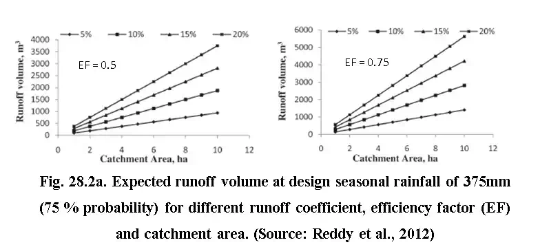
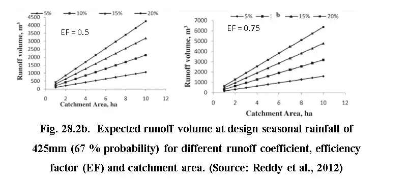
The graph provided in Fig. 22a and 2b can be used to determine the expected runoff volume to determine the net capacity of the of the proposed farm pond. This graph is however developed for seasonal rainfall of 375 mm at 75 % probability and 425 mm at 67 % probability. Similar graphs can be generated for different rainfall as well. Depending on the efficiency factor, runoff coefficient and catchment area, runoff volume is estimated and accordingly shape, size and dimension of the ponds are designed.
Shape of the Pond
Generally, the farm ponds are excavated in the shape of rectangular, square or inverted cone with circular cross section. Though, inverted cone and other curved shape ponds are difficult to construct but many times it provides higher ratio of volume to wetted surface that increases the net storage after moderating for seepage loss.
Dimension of Ponds
The optimum dimension of farm ponds should be based on the hydrological consideration and catchment area. The farm pond with respect to small catchment may not have sufficient runoff to be filled and risk of being dried during dry spell. Similarly pond with large catchment would require large water control structure and would be difficult to manage. Generally the area under dug out farm pond should not be more than 10% of the farm catchment.
Depth and Side Slope
The depth of the farm pond is decided by considering soil depth, soil type and equipment used in excavation. Though, the evaporation loss component can be minimized by increasing the depth but, from practical point of view the ideal depth is limited to 3 to 3.5 meter. Any depth beyond 4.0 meter will be uneconomical if human labour is employed in excavation.
Based on experience, it is observed that the side slope of the pond should not be steeper than the natural angle of repose of the excavated material. Table 28.1 presents the recommended side slope of farm pond for different soil as suggested by Critchley et al. (2011). Another factor while considering the side slope is duration of standing of water in the farm pond. For higher duration, flatter side slope is recommended to avoid the slippage due to saturation particularly for unlined pond.
Table 28.1. Recommended side slope
| Soil type | Slope (horizontal:vertical) |
| Clay | 1:1 to 2:1 |
| Clay loam | 1.5:1 to 2:1 |
| Sandy loam | 2:1 to 2.5:1 |
| Sandy | 3:1 |
The volume of the farm pond can be determined using eq. (28.2) as follows:
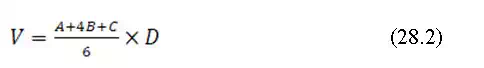
Where, is volume of exacavation (m3); is the area of excavation at ground surface (m2), is the area of exacavation at mid-depth point (D/2) (m2); C is the area at the bottom of the pond (m2) and D is the design depth (m).
28.1.5 Rectangular/Square Section Farm Pond
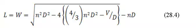
Using eq.28.2, the bottom dimension for rectangular pond is derived as

Where, , the ratio between length and width at the bottom. For square section, C will be equal to 1, Eq (28.3) would be simplified as
Example 28.1: A dugout farm pond of capacity 500 m3 is to be constructed in clay loam soil. The soil profile is such that the depth is limited to 3 m and site permits length width ratio as 1. Determine the dimension of the dugout farm ponds.
Solution:
V = 500 m3, Side slope for clay loam (n) = 2:1 (Table 28.1), D = 3 m
UseEq (28.4)to determine bottom length and width as
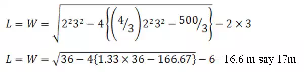
The dimension of top width would be equal to base width plus nD i.e. 17+23 = 23 m.
Similarly from Eq. (28.2), the dimension for inverted cone can be derived as
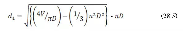
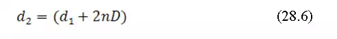
Where, is the diameter at the bottom of the pond and top diameter, can be computed as
Example 28.2: From above exercise, design an inverted cone type farm pond.
Solution:
Use Eq. (28.5)to determine the diameter of bottom, d1 as
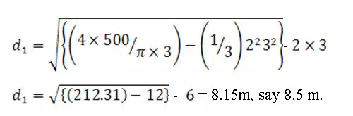
Using Eq. (28.6), the top diameter will be 14.5 m.
Economical Cross Section of Farm Ponds
Water lost from dugout ponds are mainly due to evaporation and seepage. The evaporation loss could be minimized by minimizing the surface area and volume ratio, whereas seepage losses could be minimized by reducing the ratio of wetted area and volume. Theoretically the volume of stored water per unit wetted area increases with the increase in depth of the water in ponds but at the same time increases the cost of pond lining. Thus optimization of various pond dimensions must be done for seepage reduction and cost of pond lining.
Optimization of Various Pond Dimensions
Mishra and Sharma (1994) suggested a design methodology to optimize the different pond dimensions based on designed storage volume and prevailing soil type. The optimization include following computational steps.
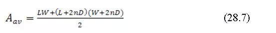
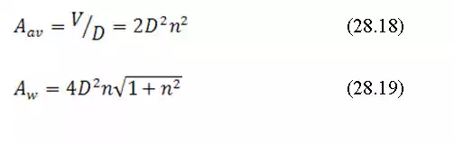
(a) Average cross-sectional area (
(b) Wetted area

(c) Storage volume, V
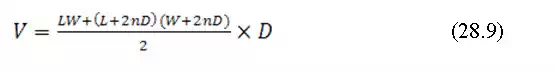
Where, L and W are the two sides of the pond bottom, D is depth of the pond and n is the side slope (horizontal: vertical::n:1)
Now expressing C=L/W i.e. W=CL, Eqs. 28.7, 28.8 and 28.9 transform as
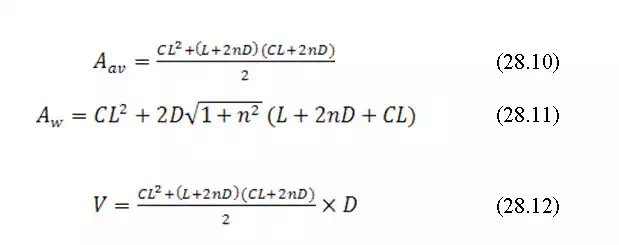
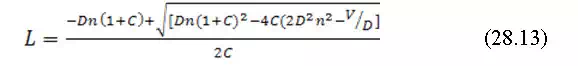
Now converting Eq.(28.12) to quadratic form and solving for L,
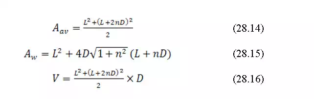
The above Eqs28.10 to 28.13 become simple for a pond with square bottom, i.e. C=1 means L=W
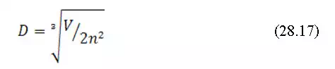
Theoretically, for a particular storage volume, the surface area of the pond is the lowest when the depth is increased to a point where the bottom surface area becomes zero. For this conditions,
Example 28.3:
A dugout farm pond of capacity 500 m3 is to be constructed in clay loam soil. Determine the optimal dimension of a farm pond.
Solution:
V = 500 m3, n = 2
Using(28.17), the optimal depth, D will be
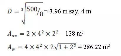
Compare this result with the exercise 28.1. In earlier exercise, the average cross sectional area was computed as 409 m2 for 3 m depth whereas in this case the average cross sectional area is only 128 m2 for 4 m depth. Just by increasing depth by one meter (if site conditions allow), one can significantly reduce evaporation loss (because surface area reduced) and seepage loss (because wetted area reduced). Moreover, the cost of lining could be minimized significantly by just increasing the depth by 1 m.
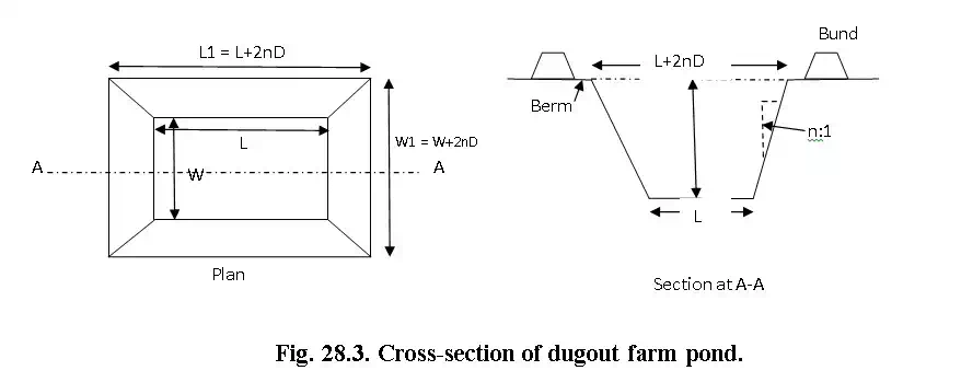
Inlet and Outlet Channel
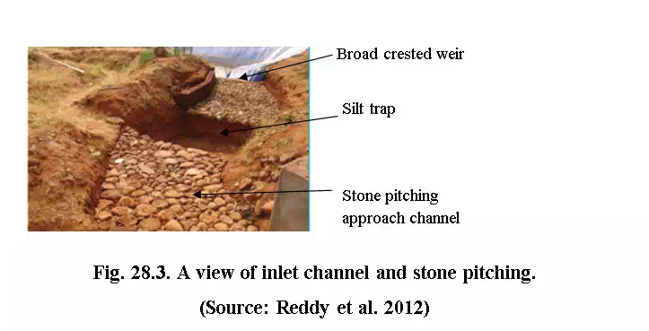
The inlet channel to the farm pond are constructed in such a way that, all the surface runoff from the catchment area to concentrate at the channel and drain into the pond. The inlet is designed as chute spillway for conveying the runoff in to the pond. While laying the inlet channel, the safe velocity of the water must be ensured to avoid channel erosion. Grasses can be grown in the channel for further protection.
Stone pitching is widely adopted to reduce the erosion from the inlet channel. The entry section is designed as a rectangular broad crested weir to allow 0.3 to 0.5 m depth of flow over 1 to 1.5 m width (Fig. 28.3).
Outlet/Waste Weir
The out let or waste weir is designed to remove the surplus runoff over and above the designed capacity of the pond. The outlet is generally located at the lower end of the pond. It should be thickly vegetated with grass to reduce the erosion. The flow through outlet should be maintained at non-erosive velocity to minimize the outlet erosion. The outlet is kept at slightly lower elevation (up to 30 cm) as compare to the inlet elevation to avoid the back water.The discharge capacity of the outlet can be assumed to be half as that of the inlet capacity as peak rate of runoff
Lining of Farm Pond
The various losses including seepage, percolation and evaporation account for as high as 60% of the gross storage. Seepage and percolation losses can be controlled using pond lining techniques. The seepage losse under different soil class is presented in Table 28.2.
Table 28.2. Seepage losses in different soil class.
| Sl. No | Type of soil | Water loss through seepage(cumec/million m2 of wetted surface) | Drop in depth per day (cm) |
| 1 | Heavy clay loam | 1.21 | 10.36 |
| 2 | Medium clay loam | 1.96 | 16.84 |
| 3 | Sandy clay loam | 2.86 | 24.61 |
| 4 | Sandy loam | 5.12 | 44.03 |
| 5 | Loose sandy soil | 6.03 | 51.80 |
| 6 | Porous gravelly soil | 10.54 | 90.65 |
Several lining techniques are available that uses the material like bricks and stone with cement and mortar. Various other techniques are also used for seepage control. Some of these are Asphalic material, paddy husk with cow dung, cement with soil mixture, fly ash mixture and bentonite treatment of pond surface. Performance of these methods varies but none of them can control seepage losses completely. The LDPE (low density poly-ethylene) film lined pond with brick overlaying as anchorage and safety from external damage to the plastic sheet can last up to 15 to 20 years and is considered as one of the permanent solution.
The advantages of LDPE film lined ponds are listed as
1. Reduction in water losses through seepage and percolation to the extent of 95%
2. Availability of water for a longer period can be ensured.
3. This type of lining provides scope to construct farm pond in porous soil as well where water retention is low
Method for LDPE lining of farm pond
For farm pond lining, the quality and strength of LDPE film depends on the capacity of pond and depth. For higher capacity say 200-1000 m3 with 3 to 3.5 m depth, minimum 500 micron thickness and 300-350 gsm (gram/m2) film is required. However, for smaller pond (capacity less than 200 m3 and depth is limited to 2.0 m) adopted in the prevailing conditions of hill and mountain agro-ecosystem of Himalayan region, 200-250 micron with 200 gsm LDPE film is sufficient for lining. The plastic film other than LDPE namely HDPE (High density polyethylene) and geo-membrane (reinforced HDPE) are also used for pond lining. The HDPE and geo-membrane film are used for lining bigger ponds where capacity is more than 1000m3. The properties of different polyethylene (PE) films are presented in Table 28.3.
Table 28.3. Properties of different PF films
| Property | Test method (ASTM coded) | Unit | Values | ||
| LDPE film 500µ | HDPE film 500µ | Geo-membrane 500µ | |||
| Material density | 1505 | g/cc | 0.92 | 0.94 | 0.94 |
| Breaking strength | 6093, 638 type IV | N/mm | 12 | 14 | 28 |
| Puncture resistance | 4833 | N | 120 | 176 | 491 |
| Tear resistance | 1004 | N | 50 | 73 | 120 |
| Bursting strength | 751 | Kg/cm2 | 4 | 4.3 | 8.5 |
| Hydro static registance | 751 | Kg/cm2 | 2 | 3 | 6 |
| Impact failure load | Gram force, Gf | 555 | 585 | >2000 |


Comments are closed.